CHAPTER 18
HOW TO CREATE BITMAPS.
THE VIDEO SCREEN:
A discussion about bitmaps automatically involves questions about communicating with the video display screen, which is why I am mentioning this here. Any object that consists of a pattern of pixels printed on the monitor screen can be interpreted as a bitmap, whether it is a picture or drawing, or a text character. The reason for using the term 'bitmap' will become clear further on.
The standard Windows operating system does not allow the programmer to directly communicate with the video screen memory array, which contains the information that is immediately put on the screen by the hardware (graphics card). Instead, a program's code has to use appropriate API functions, by means of which the system itself communicates with the screen memory block (screen buffer).
SetPixel and GetPixel are two Windows API functions, which do allow communication with the
screen on a pixel by pixel basis. The first sets a particular pixel to a particular colour, and the second retrieves the current colour of a particular pixel. These functions, however, do not involve direct communication with the screen buffer, and this results in the process being considerably slower than would be the case if direct communication with the buffer were possible.
For faster communication with the video screen, therefore, it is necessary to feed an entire array of pixel information (an entire 'map' of bits) via a single function call, rather than calling the SetPixel function separately for each pixel. To feed information for an entire array of pixels involves using Windows bitmaps, and the associated API functions. We can see here the origin and meaning of the term 'bitmap'. That is, the Windows API reference refers to bulk graphics data in this way
BITMAPS:
The basic bulk graphics data that describes a bitmap is an array of individual pixel colours which describe the colours of each of the pixels in a rectangular section of the screen.
This pixel colour information alone, however, is not sufficient to fully describe the bitmap it refers to. For example, it specifies the total number of pixels, but says nothing about how they arranged to form its width and height. 100 pixels, for example, could form a bitmap with a width and height of 10 x 10, or 5 x 20, or whatever. Thus, there must be some extra
information added to the pixel data to form a complete description of a bitmap.
This kind of extra information is referred to as a 'header'. In creating a Windows bitmap, therefore, it is necessary to create a header, which will be in the form of a data structure, and associate it with the basic pixel colour data. This header structure may be created by the programmer, or it may be internally created by Windows, depending on which of two basic kinds of bitmap is being created.
VECTOR GRAPHICS:
I will mention, here, that there is a way of describing graphics data that does not involve the concept of a bitmap. If you describe a picture by making a record of the sequence of drawing actions that created it, such as line A, from point P to point P', followed by line B from point P' to point P'', and so on, you are not describing the picture in terms of simply the colours of a rectangular array of pixels, on a horizontal line by horizontal line basis. This particular sequential method of describing a picture is referred to as 'vector graphics'. The term 'vector' is appropriately reminiscent of the object in mathematics, which is defined as a line pointing in a direction from a point P to a point P'.
Vector graphics also involves the use of mathematical shapes other than straight lines, such as curves, circles, polygons, and so on.
An advantage of vector graphics over the bitmap method of representing images is an ability to magnify an image without degrading it in the way a simple magnification of a bitmap would degrade the shapes within the image. Another advantage is that the size of the file necessary to describe the image can be much less than with a bitmap, since a bitmap has to specify the colour of every pixel within a specified rectangle, whereas a vector representation does not.
Vector graphics is a whole topic in itself, which a reader who has become familiar with basic programming can easily pursue. This text will describe only the bitmap method of representing graphics data, with the associated API functions, as normally used by the operating system
DEVICE DEPENDENT AND DEVICE INDEPENDENT BITMAPS:
These two basic kinds of bitmap arise from the fact that a bitmap is originally called 'device dependent'. That is, a programmer creates a bitmap to fit on his own particular video screen, using the colour format of that device, to produce a picture of a suitable, viewable size on the screen. However, if one tried to print such a bitmap to another device, like a printer, where the physical pixel size is much smaller, the picture could well be too tiny to be viewed properly. That is, the basic pixels, or picture dots, on a video screen are a good deal larger than the ink dots on a printed page. Also, different brands of printer can have a variety of different resolutions (dot sizes) in both the horizontal and vertical directions.
There is also the problem that the colour palette of one device, and one monitor, may be different from that in another, so that to display the bitmap data on a different monitor could unpredictably modify the interpretation of the pixel colours when they are painted on the screen. For these reasons, a bitmap created for display on a particular device is called 'device dependent'.
The operating system, however, provides for the creation of a second kind of bitmap, a 'device independent' bitmap, which contains extra information making it possible to print the bitmap at a reasonable size on any device, and to create a suitable palette for the device, if necessary.
Such extra information includes the screen resolution of the device for which the bitmap is first created, so that, by obtaining the screen resolution for some other device, like a printer, a program can calculate a multiplying factor that enables the size of the bitmap to be adjusted so that it will have a desired size on the printed page.
A device independent bitmap also contains a colour table, or colour information about all the colours used by that bitmap, sufficient to make it independent of the particular palette used by the
video monitor for which it was first created. Thus, the basic pixel colour data can be properly interpreted by any video device.
It was mentioned above that a header structure, to describe the bitmap, may or may not be created by the programmer.
In the case of a device dependent bitmap, a program's code merely feeds the bitmap's width and height information to Windows via a bitmap API function, which creates any extra, necessary, data internally.
In the case of a device independent bitmap, however, the header data structure has to be fully available to the programmer so that it can, if necessary, be used to transfer the bitmap to a different device, or saved as a file. The bitmap header is thus created by the program code first, and then transferred to the system via an API function call.
Whether a bitmap will be device dependent or device independent depends on which of the bitmap API creation functions are used to create it.
I initially intended to deal with both device dependent and device independent bitmaps in this text. The Microsoft documentation, however, leaves me with the impression that device dependent bitmaps are regarded as redundant, although the relevant bitmap API functions still exist. I have therefore decided to deal only with device independent bitmaps here.
Before dealing with the creation and display of bitmaps on the screen, we must deal with the process of specifying the colours of the bitmap pixels by means of binary number values, as every operation by a computer processor must be carried out via binary numbers.
PIXEL COLOURS:
An individual pixel on the video screen is made up of three separate components: red, green, and blue. Displaying these three together, on the screen, in close proximity, creates the effect of a single coloured pixel and, by setting each of these components, individually, to different intensities, or brightnesses, the pixel can be given an immense range of possible colours.
The binary data, used to specify the colour of a pixel, specifies the individual intensities of these three
individual colour components, and assigns to each component one byte of data. Since one byte can count up to 0FFh, or 255, this allows 255 different levels of intensity, or brightness, to be assigned to each component.
The total number of combinations of the possible intensities of the components, which is also the total number of different colours the triple component pixel can display, is 255 x 255 x 255, which is over 16.5 million possible colours.
COLOUR RESOLUTIONS AND PALETTES:
This method of displaying a colour can be referred to in terms of a 'colour resolution'. Since one byte is formed of 8 bits, the three bytes used to describe the three component colour intensities therefore use a total of 24 bits. Since we are using 24 bits to describe the colour of a single pixel, this method of describing a colour is referred to as having a 'colour resolution' of 24 bits-per-pixel.
A memory block array that uses three bytes for each pixel can become fairly large for a large sized bitmap. Many pixels in the bitmap, however, are likely to be of the same colour, and the total number of different colours used by the bitmap is very often much smaller than the total number of pixels.
Suppose, for example, you have a bitmap of 10,000 pixels that, however, uses only 100 different colours. If, therefore, you create a colour table, or palette, of 100 colours, and number them from 1 to 100, or 0 to 99, the result is that you can specify the colour of any pixel by using only one byte of data. That is, you can use an index of the colour into the table, or palette, rather than the full, three-byte colour specification. Since we now have each pixel colour specified by a one byte colour table or palette index, we can refer to this as a 'colour resolution' of only 8 bits-per-pixel,
rather than 24. It follows that the total memory necessary to specify all the individual pixel colours is now a little over 10,000 bytes, rather than the 30,000 bytes necessary at a resolution of 24 bits-per-pixel
Apart from the 24 bit-per-pixel specification, the system also uses a 32 bit-per-pixel, or doubleword, value to specify a colour, in which the high order byte is set to zero, and the other bytes specify the colour component intensities, as follows:
0x00bbggrr This is referred to as a COLORREF value, in which bb, gg, and rr, indicate the blue, green, and red components, respectively, and 00 represents the zero value of the high byte.
The operating system may have a default palette for the video display, or possibly a different bits-per-pixel specification, if not the full 24 bits-per-pixel colour resolution. The particular colour resolution of the display will not, however, be a problem when working only with device independent bitmaps, because the bitmap display API function will automatically select the closest matching colours from the system palette or colour resolution setting.
COLOUR PLANES:
The bitmap creation API function data structures will have a parameter that refers to the number of what are called 'colour planes'. This refers to a feature of the display device that relates to the manner in which it manipulates colour data.
We have already seen that a single colour is specified by three separately specified, one byte colour components: red, green, and blue. These are normally incorporated into a single 3-byte colour specification (or 4-byte, if one byte is set to zero).
Such a single specification for a colour is referred to as a single 'colour plane'. If, however, the three colour components were to be specified separately, without being combined into a single, final colour, the number of 'colour planes' would be specified as three, with one for each separate colour.
In the case of bitmaps, the colour of a pixel is normally specified as a single rgb colour, so that the number of colour planes will be 1.
THE DISPLAY DEVICE CONTEXT:
We have come across the display 'device context' before, in the context of the chapter on painting to the video screen.
The operating system has what can be considered a data structure associated with the video screen itself. This is called a 'device context'. It contains information about the system colour palette, current font, and other screen settings the system must use in order to transfer data to the video display.
Other hardware devices, like the printer, are also identified by means of their own device contexts. The
elements of a device context are not set up by a program's code. A device context is available to the program code only via its handle, or identification number, since this is all that the program requires to identify the device context to the bitmap API function. A device context's parameters can, however, be modified indirectly by suitable function calls that can change, for example, its current system font, or text colour, or other parameters.
The handle of a device context is always required by the API function used to print to any device
THE COMPATIBLE DEVICE CONTEXT:
The bitmap memory block, which contains the pixel colour data, can also be given an association with the device context chosen for the bitmap. For this purpose, a memory block can be given a device context of its own that matches the device context of the actual device, and is therefore given the appropriate name of a 'compatible' device context.
The setting up, and reconciliation of the memory device context with the actual display device context, is carried out by the operating system, and not by
the program code, which merely calls a function to instruct the operating system to set it up. Again, the program code refers to a compatible device context only by its handle, or identification number.
It is thus possible to create a bitmap in memory that can be regarded as a kind of 'virtual screen' that can be quickly printed, wholly or in part, to the actual screen, as desired. I always use this as the preferred method of printing to the screen
CREATING AND DISPLAYING DEVICE INDEPENDENT BITMAPS:
Whether a bitmap is device dependent or device independent depends on which of the bitmap creation API functions is used to create it.
The CreateDIBSection API function is used to create device independent bitmaps: This function creates the bitmap, and bitmap memory block, as an object recognisable to the operating system, and does nothing more. This means that it has to be used in conjuction with a separate API function that actually paints the pixel colour data onto the screen.
Thus, an entire bitmap is first created as a memory object. Then the pixel data must be written to the memory block before the bitmap is transferred to the screen. BitBlt is the basic API function that is used to transfer bulk graphics, or bitmap, data from a bitmap object in memory to a display.
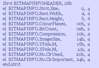
As mentioned before, the full description of a bitmap requires header data, as well as the pixel colours. The CreateDIBSection API function thus requires header data to be provided in the form of a data structure. This is a BITMAPINFO data structure, containing a BITMAPINFOHEADER data structure and a colour table. The BITMAPINFOHEADER data structure is as follows:
To create a BITMAPINFO data structure, you just add a colour table at the end of it, thus:
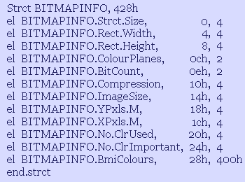
The question mark, of course, indicates the naturally arbitrary size of the colour table, as this depends on the number of colours in the individual bitmap. In the documentation, the colour table element is specified as a series of contiguous RGBQUAD data structures, one after the other, as follows:
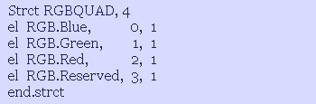
What this actually means is that each colour in the colour table can be initialised by a 4 byte COLORREF type colour specification, mentioned before, but with the red and blue colour components interchanged. If, for example, the 4 bytes in a register such as eax have the colour value, 00 rr gg bb, you can set the values in an RGBQUAD structure by simply coding
mov [RGBQUAD], eax
The memory address of RGBQUAD has blue as its first byte, with the other bytes further into, or higher in, the data structure memory, and eax has blue in its lowest byte, with the other bytes higher in the register.
When you mov eax, or any register value, into a memory address, the lowest byte is entered first, and the higher bytes follow. Thus, to fill the colour table, you would have code of the form:
mov edi,BITMAPINFO.ColourTable
mov esi, some colour table source address
for (some number of colours)
set.d '=',[edi],[esi]
add.d edi,4, esi,4 ;next RGBQUAD address
end.for
The BITMAPINFO structure does not have to have a colour table, in which case the colour table element can be simply set to zero. It depends on the way in which the pixel colours are described. If the pixel colours are fully specified, in a 24 or 32 bit-per-pixel format, there is no colour table, because each pixel colour is declared directly. If there is a colour table, the pixel colours are specified indirectly, as indices into the colour table, and require less than the full 24 or 32 bits-per-pixel. This is a matter that depends on the number of colours used in the bitmap.
If the bitmap has less than 256 colours, for example, the maximum colour number, or index into the table, will be less than 256, and all the pixel colours can be specified by only one byte each, or 8 bits-per-pixel.
If the colour table has more than 256 colours, one byte is not sufficient to specify the maximum index number. Here, one cannot simply specify a word sized, or 16-bit, index into the colour table. This is because 16 bits-per-pixel is a resolution used to directly specify 16-bit colour, also called 'high colour' in the pixel array, for 16-bit colour displays. By setting a flag, however, it is possible to use a 16-bit index into the display device context current palette. Thus, you would have to use the colour table to create a system palette, and select it into the display device context, in order to effectively specify 16-bit indices into the colour table. Palettes, however, are obsolete in modern full colour displays, and specifying 16-bit colour is also problematic.
The above discussion means that, if the bitmap has more than 256 colours, it will be necessary to fully specify the pixel colours directly, and not via a colour table.
Using a colour table reduces the size of the bitmap pixels array memory block but, if this is not a necessity, the full 32 bits-per-pixel specification, with no colour table, is the least complicated. However, if the bitmap is to be saved as a file, the lesser file size that the colour table method allows may be important.
The following code example creates a device independent bitmap, with direct 32-bit pixel colour specification, and no colour table.
The code first initialises the BITMAPINFO data structure. The Strct.size element specifies the size of the BITMAPINFOHEADER part of the structure (excluding the colour table element), and is therefore always 28h. The Bitmap.Width element is straightforward, but not so the specification of the bitmap height.
You can see that, at the start, the [BITMAP.Height] value is subtracted from zero. This is done in order to give the height a negative value.
mov ecx,0
sub ecx,[BITMAP.Height]
;
eq [BITMAPINFO.Strct.size], '=', 28h
eq [BITMAPINFO.Bitmap.Width], '=', [BITMAP.Width]
eq [BITMAPINFO.Bitmap.Height], '=', ecx
eq.w [BITMAPINFO.ColourPlanes], '=', 1
eq.w [BITMAPINFO.BitCount], '=', 32
eq [BITMAPINFO.Compression], '=', BI_RGB
eq [BITMAPINFO.ImageSize], '=', 0
eq [BITMAPINFO.YPxls.M], '=', 0
eq [BITMAPINFO.XPxls.M], '=', 0
eq [BITMAPINFO.No.ClrUsed], '=', 0
eq [BITMAPINFO.No.ClrImportant], '=', 0
eq [BITMAPINFO.ColourTable], '=', 0
;
api GetDC,[WINDOW.Handle]
mov [DISPLAY.DC],eax
mov ecx,DIB_RGB_COLORS
api CreateDIBSection,[DISPLAY.DC],BITMAPINFO,ecx,BITMAP.BitsAddress,0,0
mov [BITMAP.Handle],eax
api ReleaseDC,[WINDOW.Handle],[DISPLAY.DC]
mov [DISPLAY.DC],dword 0
For some reason, the default origin of a device independent bitmap is the bottom left corner, but this can be converted to an origin at the top left corner by giving the bitmap height a negative value. The bottom left corner specified bitmap is also called a 'bottom up' bitmap, with the top left corner specified bitmap being called a 'top down' bitmap.
As mentioned elsewhere, negative values are an interpretation of values above half a full dword value plus 1, inclusive, or half of 100000000h, which is 80000000h, inclusive.
The negative of a value can be obtained by subtracting it from zero, and this negative values system can be used in any situation where values will never reach a figure of 80000000h or higher (about 2 billion).
The colour planes value is set to 1, as usual, and the BitCount to 32 bits-per-pixel.
A device independent bitmap can be compressed, if desired. One possible method involves the fact that a bitmap with a large, single colour background area will have many successive pixels all of the same colour. Thus, instead of specifying the colour of every pixel independently, the pixel array can have entries of the form (number of pixels),(pixel colour), (number of pixels),(pixel colour)�, which means that, each time, all the (number of pixels) pixels should be set to the same (pixel colour) value. This method can significantly reduce the size of the pixel colours array. The BI_RGB flag, however, secifies an uncompressed bitmap, which is the straightforward case we are dealing with. With BI_RGB bitmaps, the ImageSize element can be set to zero.
The values of the other elements are not essential,
and can be set to zero.
The XPxls.M and YPxls.M elements specify the horizontal and vertical pixels-per-metre values, respectively, of the display for which the bitmap was created, and are useful if a bitmap has to be saved as a file, or printed to a printer, because they give an indication of the physical size, rather than the screen size, of the bitmap on the display. These values can be obtained via the GetDeviceCaps API function.
The CreateDIBSection function requires the display device context as its first parameter. The other parameters are BITMAPINFO (the BITMAPINFO structure address), a DIB_RGB_COLORS flag, the bitmap pixels array address, and two file mapping parameters, which are set to zero.
The DIB_RGB_COLORS flag indicates that the bitmap specifies full RGB colour values, whether in a colour table, or directly in the pixels colour array. A DIB_PAL_COLORS flag would specify that the pixels array contained 16-bit indices into the display device context palette. As mentioned before, it is better, or less problematic, to use full RGB colour values.
CreateDIBSection returns a handle to the bitmap in eax, and also creates a system memory block for the bitmap and provides the address of the start of the memory block so that a programmer can directly write to the memory block, to initialise or update it.
BITMAP.BitsAddress, is the address of a variable into which the CreateDIB section writes the address of the memory block, which can therefore be obtained as [BITMAP.BitsAddress].
DEVICE INDEPENDENT BITMAPS WITH COLOUR TABLES:
As mentioned in the foregoing discussion, a device independent bitmap with not more than 256 colours can be defined with the use of a colour table, with the pixel colours specified as indices into the colour table. If it has more than 256 colours, however, it is necessary to specify the pixel colours directly.
This, of course, is only while you are using the Windows operating system bitmap format. If you create your own code, with its own files, you can create a colour table of any size and use, for example,
16-bit indices into the colour table to specify the pixel colours. Such a method can be used to save a bitmap to a file in your own, non-bmp format. However, when printing such a bitmap to the screen, the 16-bit indices will have to be converted to a direct full colour specification, for use by the BitBlt function.
The following code uses a colour table to define a device independent bitmap with less than 256 colours:
mov ecx,0
sub ecx,[BITMAP.Height]
;
eq [BITMAPINFO.Strct.size], '=', 28h
eq [BITMAPINFO.Bitmap.Width], '=', [BITMAP.Width]
eq [BITMAPINFO.Bitmap.Height], '=', ecx
eq.w [BITMAPINFO.ColourPlanes], '=', 1
eq.w [BITMAPINFO.BitCount], '=', 8
eq [BITMAPINFO.Compression], '=', BI_RGB
eq [BITMAPINFO.ImageSize], '=', 0
eq [BITMAPINFO.YPxls.M], '=', 0
eq [BITMAPINFO.XPxls.M], '=', 0
eq [BITMAPINFO.No.ClrUsed], '=', 0
eq [BITMAPINFO.No.ClrImportant], '=', 0
;
ii.. mov edi,BITMAPINFO.ColourTable, mov esi,(some colours source)
for [BITMAP.ColoursNo]
set.d '=',[edi],[esi]
add.d edi,4, esi,4
end.for
api GetDC,[WINDOW.Handle]
mov [DISPLAY.DC],eax
mov ecx,DIB_RGB_COLORS
api CreateDIBSection,[DISPLAY.DC],BITMAPINFO,ecx,BITMAP.BitsAddress,0,0
mov [BITMAP.Handle],eax
api ReleaseDC,[WINDOW.Handle],[DISPLAY.DC]
mov [DISPLAY.DC],dword 0
Here, the BITMAPINFO.BitCount element of the data structure is set to 8 bits-per-pixel, to indicate single byte indices into the colour table in the pixel colours array.
the BITMAPINFO.ColourTable element is not set to
0, as before. Instead, the colours used by the bitmap are written into this location from wherever you have originally specified the bitmap colours, and thus form the BITMAPINFO data structure colour table.
DESTROYING OBJECTS TO FREE UP RESOURCES:
Creating objects, such a bitmaps and device contexts, which are given handles by the operating system, automatically requires the system to assign the necessary resources to set up the system internal data structures and memory required. For this reason, it is necessary for a program to destroy such objects, when no longer needed, in order to allow the system to free up these resources so that they can be used by other programs.
If this were not done, each program opened by the user would cumulatively consume the system's resources until, possibly, none were left for another program to use. Destroying an object need not apply immediately to every resource used by a program and some resources, such as bitmaps, can be retained and destroyed only when the program exits.
In the above code, used to create and display a bitmap on the screen, the compatible device and display device contexts are destroyed by the DeleteDC and ReleaseDC API functions, respectively.
Bitmaps, on the other hand, can, and should, be kept and reused, rather than being destroyed and recreated each time they are needed, since they occupy a relatively large amount of memory. This may, indeed, seem contradictory but it is necessitated by some kind of bug in the Windows operating system memory management. A large number of successive creations and destructions of such objects appear to eventually degrade the management of the system memory, resulting in an eventual failure of the bitmap API functions.
For this reason, it is better, at the beginning of a program, to create a sufficient number of bitmaps, and keep reusing them, and then destroy them only when the program exits.
These considerations also apply, by the way, to the creation and destruction of whatever fonts the program may use.
For a bitmap to be destroyed by means of the DeleteObject API function, it must not have been selected into a device context, or the function will fail. The bitmap must first be deselected from its device context before it is deleted. Here, in fact, we encounter another of those potentially frustrating problems over which a person new to programming can waste a good deal of time.
It is quite easy to assume that there should be a DeselectObject function to deselect a bitmap from a device context. A search for such a function will reveal, however, that no such function appears to exist, and this is because, in fact, a bitmap is also deselected from a device context by using the same function, SelectObject, by means of which it was originally selected into it. This works as follows:
A call to SelectObject provides a return value, which is a handle to the object being replaced by the new object being selected. This may seem puzzling if a device context has only just been created, and no object has yet been selected into it, so how can there be any object in it to replace? There is, of course, no previously selected object, but a handle is nonetheless returned, just as if there is. The returned handle is, in fact, only a placeholder for an object, but can nevertheless be used just as if it were an object like the object that is replacing it. Thus, we use SelectObject, to select the bitmap into its device context, and [BITMAP.Handle.sv] is used to save the placeholder handle (sv means 'saved'). Then, if we reuse SelectObject to select the placeholder back into the device context, it replaces our selected bitmap, which is thus automatically 'deselected'.
THE RELATIVE MERITS OF DEVICE INDEPENDENT AND DEVICE DEPENDENT BITMAPS:
The Windows API documentation appears to discourage the use of device dependent bitmaps and, indeed, you can quite readily work only with device independent bitmaps, and never use the device dependent variety.
Probably the only advantage of using device dependent bitmaps is speed of operation. If you have a bitmap compatible with the display, the operating system has less work to do to paint it to the screen. Indeed, the Microsoft documentation refers to the device dependent function, SetBitmapBits, as obsolete, in favour of the device independent equivalent, SetDIBits. Nevertheless, the API functions for device dependent bitmaps are still available, probably in case speed of operation is important, though it will often not matter.
In general, device independent bitmaps are easier to use, because one does not have to worry about whether or not the bitmap, as originally created, is compatible with the device. The operating system automatically matches an RGB colour specification
to the colour format of the display.
If, for example, you specify a full 32-bit colour resolution for the pixels array, but the display is only a 16-bit, high colour display, the BitBlt function will automatically match the 32-bit colour to the nearest 16-bit colour available.
As mentioned, this extra work takes time, and makes the operation correspondingly slower. The CreateDIBSection API function also provides the address of the bitmap bits, which allows direct access to the pixel colours in memory, whereas API functions have to be used to indirectly access the bitmap bits in the case of device dependent API functions. There are also problems updating device dependent bitmaps, if they are not destroyed and recreated, but I need not deal further with that here.
On the whole, it is preferable to use device independent bitmaps as the normal method of working with system compatible bitmaps.
SCANNING MEMORY TO CREATE RECTANGLES:
The pixel data for a bitmap in memory is merely a succession of values in a linear array of memory addresses. If this is to be used to represent a rectangular bitmap, with width and height W and H respectively, the linear array has to be given a rectangular interpretation by assigning the first W number of addresses in the array as the first line in the rectangle, and the next W number of addresses as the second line, and so on, until this has been done H times. This is straightforward, but difficulties can arise when one wants to scan a sub-rectangle within the overall rectangle.
Suppose, therefore, we want to scan a sub-rectangle of width w and height h, within the above rectangle of width W and height H, at horizontal and vertical coordinates x and y, respectively, measured from the top left hand corner of the large rectangle.
The top left corner of the large rectangle is the first address in the array, to which we will therefore assign the coordinates 0,0. The address at W-1 from the start of the array is the address of the last pixel of the first line, with coordinates (W-1),0. The address at W is then the first pixel of the second line, with coordinates 0,1. In general, (any pixel address + W) gives the address of the pixel immediately below it on the next line. Therefore, to get the first pixel of the line in the large rectangle which contains the first line of the sub-rectangle, at vertical coordinate y, we must add W, y times, to the starting address of the array.
Then, to get the first horizontal pixel of the sub-rectangle, at coordinate x, we must add x addresses to this, as shown below (assuming each pixel requires 4 bytes of memory to describe its colour).
After the above procedure, esi indicates the address of the start of the small sub-rectangle. If it is necessary to transfer this sub-rectangle to the screen, or wherever, we must scan it.
mov esi, [ARRAY.Address]
for y
add esi,4
end.for
mov ecx,x
shl ecx,2 ;multiply by 4 to give 4 bytes to each x
add esi,ecx
The first w pixels starting at esi, inclusive, represent the first line of the sub-rectangle, which means that the last pixel of the first line is at (esi + (w-1)), and not at (esi + w). To get the next line of the sub-rectangle, we must go back to the start of the line of the small rectangle, and add the width W of the large rectangle, and not the width w of the sub-rectangle, because each line of the small rectangle is a part of a line in the large rectangle.
The above procedure will occur h times, to scan all h lines in the small rectangle, as follows:
mov ecx,W
shl ecx,2 ;multiply by 4 to give 4 bytes to each of the W pixels
mov edi, [DESTINATION.Address]
for h
push esi ;save the current address of start of a small line
for w
set.d '=',[edi],[esi]
add.d edi,4, esi,4
end.for
pop esi ;go back to start of small line
add esi,ecx ;get next small line within large rectangle (ecx = W*4)
end.for
CREATING BMP FILES:
To create *.bmp bitmap files, you have to use a device independent bitmap, and include the BITMAPINFO data structure in the file. However, the file must also have a file type data structure at the start, called a BITMAPFILEHEADER structure, as follows:
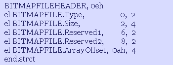
The BITMAPFILEHEADER file header is followed by a BITMAPINFO structure, which includes a colour table, if there is one, and this is then followed by the bitmap pixels colours array.
The following code creates a bmp file with a bitmap having a full 32-bit pixel colour specification, and no colour table.
It dynamically creates a temporary memory block, using GobalAlloc, in order to assemble the file data and then upload it the the hard disk.
The Ofs.* are equate names which refer to the relevant data structure elements as offsets from the address in edi. These equates have to be previously defined in the data section of your code. For example, the BITMAPFILE.Reserved1 element is at offset 6 from the start of the file header, so the corresponding equate would be:
Ofs.BITMAPFILE.Reserved1 equ 6
and so on, for the others.
ii.. mov ecx,[BITMAP.Size], shl ecx,2
eq edx, '=', 0eh, '+', 28h, '+', 4
eq [FILE.Size], '=', 0eh, '+', 28h,'+', ecx
mov edi,BITMAPFILE
eq.w [edi+Ofs.BITMAPFILE.Type], '=', 'BM'
eq [edi+Ofs.BITMAPFILE.Size], '=', [FILE.Size]
eq.w [edi+Ofs.BITMAPFILE.Reserved1], '=', 0
eq.w [edi+Ofs.BITMAPFILE.Reserved2], '=', 0
eq [edi+Ofs.BITMAPFILE.ArrayOffset], '=', edx
add edi,0eh
eq [edi+Ofs.BITMAPINFO.Strct.size], '=', [BITMAPINFO.Strct.size]
eq [edi+Ofs.BITMAPINFO.Rect.Width], '=', [BITMAPINFO.Rect.Width]
eq [edi+Ofs.BITMAPINFO.Rect.Height], '=', [BITMAPINFO.Rect.Height]
eq [edi+Ofs.BITMAPINFO.ColourPlanes], '=', [BITMAPINFO.ColourPlanes]
eq [edi+Ofs.BITMAPINFO.BitCount], '=', 24
eq [edi+Ofs.BITMAPINFO.Compression], '=', [BITMAPINFO.Compression]
eq [edi+Ofs.BITMAPINFO.ImageSize], '=', [BITMAPINFO.ImageSize]
eq [edi+Ofs.BITMAPINFO.YPxls.M], '=', [BITMAPINFO.YPxls.M]
eq [edi+Ofs.BITMAPINFO.XPxls.M], '=', [BITMAPINFO.XPxls.M]
eq [edi+Ofs.BITMAPINFO.No.ClrUsed], '=', [BITMAPINFO.No.ClrUsed]
eq [edi+Ofs.BITMAPINFO.No.ClrImportant], '=', [BITMAPINFO.No.ClrImportant]
eq [edi+Ofs.BITMAPINFO.bmiColours], '=', 0
add edi,28h
mov esi,[BITMAP.BitsAddress]
for [BITMAP.Size]
set.b '==&',[esi],[edi], [esi+1],[edi+1], [esi+2],[edi+2]
add.d esi,4, edi,3
end.for
push.d [WINDOW.Handle], [MESSAGE],[WPARAM],[LPARAM]
call .InitOpenFilenameStructure
api GetSaveFileName,OPENFILENAME
cmp eax,TRUE
jne near .exit_scf
api CreateFile, FILE.SelectedFile, GENERIC_WRITE+GENERIC_READ, 0, 0, OPEN_ALWAYS, FILE_ATTRIBUTE_NORMAL, 0
mov [FILE.Handle],eax
api SetFilePointer, [FILE.Handle],0,0,FILE_BEGIN
api SetEndOfFile,[FILE.Handle]
api WriteFile,[FILE.Handle],BITMAPFILE,[FILE.Size],FILE.BytesWritten,0
api CloseHandle,[FILE.Handle]
.exit_scf:
pop.d [LPARAM],[WPARAM],[MESSAGE],[WINDOW.Handle]
ret
Part I: Part I Introduction
Chapter 1: Binary numbers, code, and procedures
Chapter 3: Assembly Language
Chapter 4: Assembly Language Code example
Chapter 5: Macros and HLA
Chapter 6: HLA code example
Chapter 7: The Windows operating system
Chapter 8: Data Structures
Chapter 9: How to Create a Windows Program
Chapter 10: How to Create an Exe File
Chapter 11: Structured Programming and OOP
Part II: Part II Introduction
Chapter 12: Debugging a Windows Program Code
Chapter 13: Painting the Window Client Area
Chapter 14: Creating Window Menus
Chapter 15: How to Create Toolbars
Chapter 16: How to Create Popup Menus
Chapter 17: About the Windows Clipboard
Chapter 18: How to Create Bitmaps
Chapter 19: Icons and the Ico Format
Chapter 20: Common Dialog Boxes
Chapter 21: Working with Files
Chapter 22: Scrollbars and Scrolling
Chapter 23: How to Send Data to the Printer
Chapter 24: Miscellaneous Topics
© Alen, June 2014
alen@alenspage.net
Material on this page may be reproduced
for personal use only.